Vytvoření vlastních backendů a transpilace vůči nim
# Added by doQumentation — required packages for this notebook
!pip install -q numpy qiskit rustworkx
# Don't use SVGs for this file because the images are too large,
# and the SVGs are much larger than their PNGs equivalents.
%config InlineBackend.figure_format='png'
```json

{/* cspell:ignore multichip interchip Lasciate ogne speranza voi ch'intrate */}
{/*
  DO NOT EDIT THIS CELL!!!
  This cell's content is generated automatically by a script. Anything you add
  here will be removed next time the notebook is run. To add new content, create
  a new cell before or after this one.
*/}

<details>
<summary><b>Verze balíčků</b></summary>

Kód na této stránce byl vyvinut s použitím následujících závislostí.
Doporučujeme používat tyto nebo novější verze.
qiskit[all]~=2.4.0
</details>
{/* cspell:ignore LOCC */}

Jednou z nejsilnějších vlastností Qiskitu je schopnost podporovat jedinečné konfigurace zařízení. Qiskit je navržen tak, aby byl nezávislý na poskytovateli kvantového hardwaru, který používáš, a poskytovatelé mohou objekt `BackendV2` konfigurovat podle svých vlastních specifických vlastností zařízení. Toto téma ukazuje, jak nakonfigurovat vlastní Backend a jak vůči němu transpilovat kvantové Circuit.

Můžeš vytvářet jedinečné objekty `BackendV2` s různými geometriemi nebo bázovými hradly a transpilovat své Circuit s přihlédnutím k těmto konfiguracím. Níže uvedený příklad pokrývá Backend s nepropojenou mřížkou Qubitů, jehož bázové hradla se liší podél hran oproti vnitřní části.
## Pochopení rozhraní Provider, BackendV2 a Target \{#understand-the-provider-backendv2-and-target-interfaces}

Než začneš, je užitečné pochopit použití a účel objektů [`Provider`](../api/qiskit/providers), [`BackendV2`](../api/qiskit/qiskit.providers.BackendV2) a [`Target`](../api/qiskit/qiskit.transpiler.Target).

- Pokud máš kvantové zařízení nebo simulátor, který chceš integrovat do Qiskit SDK, musíš napsat vlastní třídu `Provider`. Tato třída slouží jedinému účelu: získat objekty backendů, které poskytuje. Zde se řeší veškeré potřebné přihlašovací a/nebo autentizační úkoly. Po vytvoření instance poskytne objekt poskytovatele seznam backendů a také možnost získat/vytvořit instance backendů.

- Dále třídy backendů poskytují rozhraní mezi Qiskit SDK a hardwarem nebo simulátorem, který bude spouštět Circuit. Obsahují veškeré informace potřebné k popisu Backendu pro Transpiler, aby mohl optimalizovat jakýkoli Circuit podle jeho omezení. `BackendV2` se skládá ze čtyř hlavních částí:
  - Vlastnost [`Target`](../api/qiskit/qiskit.transpiler.Target), která obsahuje popis omezení Backendu a poskytuje model Backendu pro Transpiler
  - Vlastnost `max_circuits`, která definuje limit počtu Circuit, které může Backend spustit v jedné úloze
  - Metoda `run()`, která přijímá odesílání úloh
  - Sada `_default_options` pro definování uživatelsky konfigurovatelných možností a jejich výchozích hodnot
## Vytvoření vlastního BackendV2 \{#create-a-custom-backendv2}

Objekt `BackendV2` je abstraktní třída používaná pro všechny objekty backendů vytvořené poskytovatelem (buď v rámci `qiskit.providers` nebo jiné knihovny, jako je [`qiskit_ibm_runtime.IBMBackend`](../api/qiskit-ibm-runtime/ibm-backend)). Jak bylo zmíněno výše, tyto objekty obsahují několik atributů, včetně [`Target`](https://docs.quantum.ibm.com/api/qiskit/qiskit.transpiler.Target). `Target` obsahuje informace, které specifikují atributy Backendu – jako je [`Coupling Map`](https://docs.quantum.ibm.com/api/qiskit/qiskit.transpiler.CouplingMap), seznam [`Instructions`](https://docs.quantum.ibm.com/api/qiskit/qiskit.circuit.Instruction) a další – pro Transpiler. Kromě `Target` lze také definovat detaily na úrovni pulzů, jako je [`DriveChannel`](https://docs.quantum.ibm.com/api/qiskit/1.4/qiskit.pulse.channels.DriveChannel) nebo [`ControlChannel`](https://docs.quantum.ibm.com/api/qiskit/1.4/qiskit.pulse.channels.ControlChannel).

Následující příklad demonstruje toto přizpůsobení vytvořením simulovaného víčipového Backendu, kde každý čip má konektivitu heavy-hex. Příklad specifikuje sadu dvouQubitových hradel Backendu jako [`CZGates`](../api/qiskit/qiskit.circuit.library.CZGate) uvnitř každého čipu a [`CXGates`](../api/qiskit/qiskit.circuit.library.ECRGate) mezi čipy. Nejprve vytvoř vlastní `BackendV2` a přizpůsob jeho `Target` jednoqubitovými a dvouqubitovými hradly podle dříve popsaných omezení.

<Admonition type="tip" title="Knihovna graphviz">
Vykreslení mapy spojení vyžaduje instalaci knihovny [`graphviz`](https://graphviz.org/).
</Admonition>

```python
import numpy as np
import rustworkx as rx

from qiskit.providers import BackendV2, Options
from qiskit.transpiler import Target, InstructionProperties
from qiskit.circuit.library import XGate, SXGate, RZGate, CZGate, ECRGate
from qiskit.circuit import Measure, Delay, Parameter, Reset
from qiskit import QuantumCircuit, transpile
from qiskit.visualization import plot_gate_map

class FakeLOCCBackend(BackendV2):
    """Fake multi chip backend."""

    def __init__(self, distance=3, number_of_chips=3):
        """Instantiate a new fake multi chip backend.

        Args:
            distance (int): The heavy hex code distance to use for each chips'
                coupling map. This number **must** be odd. The distance relates
                to the number of qubits by:
                :math:`n = \\frac{5d^2 - 2d - 1}{2}` where :math:`n` is the
                number of qubits and :math:`d` is the ``distance``
            number_of_chips (int): The number of chips to have in the multichip backend
                each chip will be a heavy hex graph of ``distance`` code distance.
        """
        super().__init__(name="Fake LOCC backend")
        # Create a heavy-hex graph using the
        # rustworkx library, then instantiate a new target
        self._graph = rx.generators.directed_heavy_hex_graph(
            distance, bidirectional=False
        )
        num_qubits = len(self._graph) * number_of_chips
        self._target = Target(
            "Fake multi-chip backend", num_qubits=num_qubits
        )

        # Generate instruction properties for single qubit gates and a measurement, delay,
        #  and reset operation to every qubit in the backend.
        rng = np.random.default_rng(seed=12345678942)
        rz_props = {}
        x_props = {}
        sx_props = {}
        measure_props = {}
        delay_props = {}

        # Add 1q gates. Globally use virtual rz, x, sx, and measure
        for i in range(num_qubits):
            qarg = (i,)
            rz_props[qarg] = InstructionProperties(error=0.0, duration=0.0)
            x_props[qarg] = InstructionProperties(
                error=rng.uniform(1e-6, 1e-4),
                duration=rng.uniform(1e-8, 9e-7),
            )
            sx_props[qarg] = InstructionProperties(
                error=rng.uniform(1e-6, 1e-4),
                duration=rng.uniform(1e-8, 9e-7),
            )
            measure_props[qarg] = InstructionProperties(
                error=rng.uniform(1e-3, 1e-1),
                duration=rng.uniform(1e-8, 9e-7),
            )
            delay_props[qarg] = None
        self._target.add_instruction(XGate(), x_props)
        self._target.add_instruction(SXGate(), sx_props)
        self._target.add_instruction(RZGate(Parameter("theta")), rz_props)
        self._target.add_instruction(Measure(), measure_props)
        self._target.add_instruction(Reset(), measure_props)

        self._target.add_instruction(Delay(Parameter("t")), delay_props)
        # Add chip local 2q gate which is CZ
        cz_props = {}
        for i in range(number_of_chips):
            for root_edge in self._graph.edge_list():
                offset = i * len(self._graph)
                edge = (root_edge[0] + offset, root_edge[1] + offset)
                cz_props[edge] = InstructionProperties(
                    error=rng.uniform(7e-4, 5e-3),
                    duration=rng.uniform(1e-8, 9e-7),
                )
        self._target.add_instruction(CZGate(), cz_props)

        cx_props = {}
        # Add interchip 2q gates which are ecr (effectively CX)
        # First determine which nodes to connect
        node_indices = self._graph.node_indices()
        edge_list = self._graph.edge_list()
        inter_chip_nodes = {}
        for node in node_indices:
            count = 0
            for edge in edge_list:
                if node == edge[0]:
                    count += 1
            if count == 1:
                inter_chip_nodes[node] = count
        # Create inter-chip ecr props
        cx_props = {}
        inter_chip_edges = list(inter_chip_nodes.keys())
        for i in range(1, number_of_chips):
            offset = i * len(self._graph)
            edge = (
                inter_chip_edges[1] + (len(self._graph) * (i - 1)),
                inter_chip_edges[0] + offset,
            )
            cx_props[edge] = InstructionProperties(
                error=rng.uniform(7e-4, 5e-3),
                duration=rng.uniform(1e-8, 9e-7),
            )

        self._target.add_instruction(ECRGate(), cx_props)

    @property
    def target(self):
        return self._target

    @property
    def max_circuits(self):
        return None

    @property
    def graph(self):
        return self._graph

    @classmethod
    def _default_options(cls):
        return Options(shots=1024)

    def run(self, circuit, **kwargs):
        raise NotImplementedError(
            "This backend does not contain a run method"
        )
Vizualizace backendů
Graf konektivity této nové třídy si můžeš prohlédnout pomocí metody plot_gate_map() z modulu qiskit.visualization. Tato metoda spolu s plot_coupling_map() a plot_circuit_layout() jsou užitečné nástroje pro vizualizaci uspořádání Qubitů v Backendu a také toho, jak je Circuit rozmístěn přes Qubity Backendu. Tento příklad vytváří Backend obsahující tři malé heavy-hex čipy. Specifikuje sadu souřadnic pro uspořádání Qubitů a sadu vlastních barev pro odlišení dvouqubitových hradel.
backend = FakeLOCCBackend(3, 3)

target = backend.target
coupling_map_backend = target.build_coupling_map()

coordinates = [
    (3, 1),
    (3, -1),
    (2, -2),
    (1, 1),
    (0, 0),
    (-1, -1),
    (-2, 2),
    (-3, 1),
    (-3, -1),
    (2, 1),
    (1, -1),
    (-1, 1),
    (-2, -1),
    (3, 0),
    (2, -1),
    (0, 1),
    (0, -1),
    (-2, 1),
    (-3, 0),
]

single_qubit_coordinates = []
total_qubit_coordinates = []

for coordinate in coordinates:
    total_qubit_coordinates.append(coordinate)

for coordinate in coordinates:
    total_qubit_coordinates.append(
        (-1 * coordinate[0] + 1, coordinate[1] + 4)
    )

for coordinate in coordinates:
    total_qubit_coordinates.append((coordinate[0], coordinate[1] + 8))

line_colors = ["#adaaab" for edge in coupling_map_backend.get_edges()]
ecr_edges = []

# Get tuples for the edges which have an ecr instruction attached
for instruction in target.instructions:
    if instruction[0].name == "ecr":
        ecr_edges.append(instruction[1])

for i, edge in enumerate(coupling_map_backend.get_edges()):
    if edge in ecr_edges:
        line_colors[i] = "#000000"
print(backend.name)
plot_gate_map(
    backend,
    plot_directed=True,
    qubit_coordinates=total_qubit_coordinates,
    line_color=line_colors,
)
Fake LOCC backend
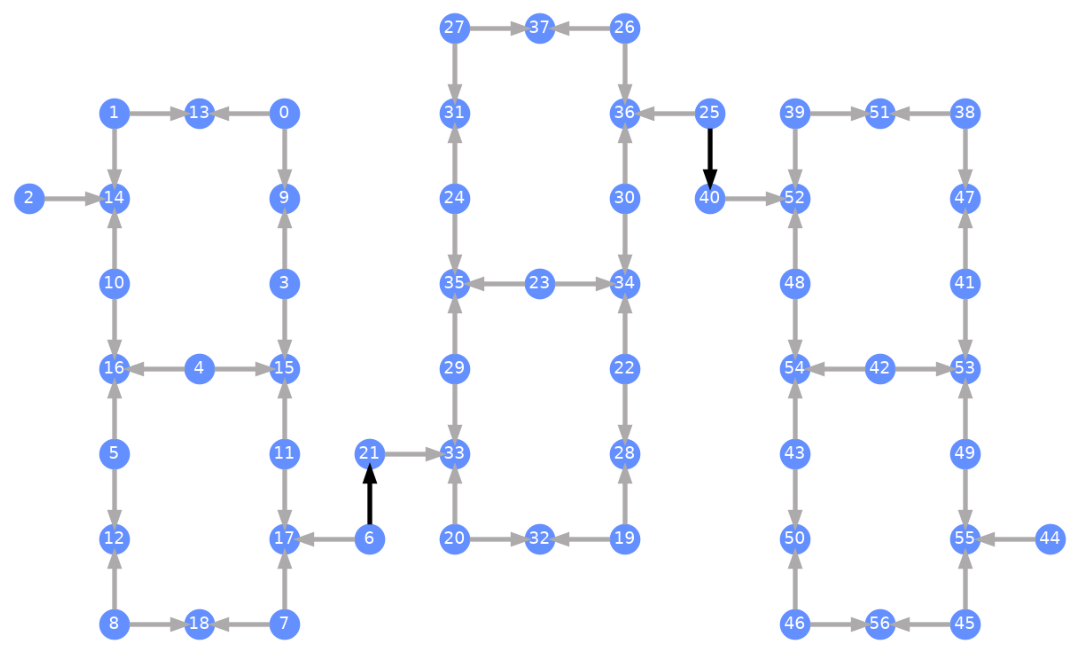
Každý qubit je označen a barevné šipky znázorňují dvouqubitová hradla. Šedé šipky jsou CZ hradla a černé šipky jsou mezičipová CX hradla (ta spojují Qubity a ). Směr šipky udává výchozí směr, ve kterém jsou tato hradla prováděna; specifikuje, které Qubity jsou ve výchozím nastavení řídící/cílové pro každý dvouqubitový kanál.
Transpilace vůči vlastním backendům
Nyní, když byl definován vlastní Backend s vlastním jedinečným Target, je přímočaré transpilovat kvantové Circuit vůči tomuto Backendu, protože všechna relevantní omezení (bázová hradla, konektivita Qubitů apod.) potřebná pro průchody Transpileru jsou obsažena v tomto atributu. Následující příklad sestaví Circuit, který vytvoří velký GHZ stav, a transpiluje ho vůči výše zkonstruovanému Backendu.
from qiskit.transpiler import generate_preset_pass_manager

num_qubits = 50
ghz = QuantumCircuit(num_qubits)
ghz.h(range(num_qubits))
ghz.cx(0, range(1, num_qubits))
op_counts = ghz.count_ops()

print("Pre-Transpilation: ")
print(f"CX gates: {op_counts['cx']}")
print(f"H gates: {op_counts['h']}")
print("\n", 30 * "#", "\n")

pm = generate_preset_pass_manager(optimization_level=3, backend=backend)
transpiled_ghz = pm.run(ghz)
op_counts = transpiled_ghz.count_ops()

print("Post-Transpilation: ")
print(f"CZ gates: {op_counts['cz']}")
print(f"ECR gates: {op_counts['ecr']}")
print(f"SX gates: {op_counts['sx']}")
print(f"RZ gates: {op_counts['rz']}")
Pre-Transpilation:
CX gates: 49
H gates: 50

 ##############################
Post-Transpilation:
CZ gates: 146
ECR gates: 6
SX gates: 302
RZ gates: 250
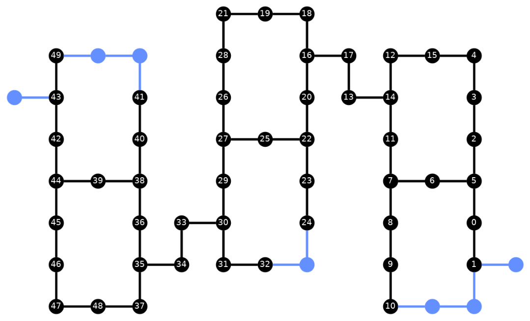
Transpilovaný Circuit nyní obsahuje kombinaci hradel CZ a ECR, které jsme specifikovali jako bázová hradla v Target Backendu. Je v něm také výrazně více hradel, než s jakými jsme začali, kvůli nutnosti vkládat instrukce SWAP po volbě rozmístění. Níže je vizualizační nástroj plot_circuit_layout() použit k zobrazení toho, které Qubity a dvouqubitové kanály byly v tomto Circuit využity.
from qiskit.visualization import plot_circuit_layout

plot_circuit_layout(
    transpiled_ghz, backend, qubit_coordinates=total_qubit_coordinates
)
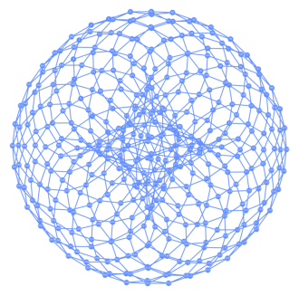
Vytváření jedinečných backendů
Balíček rustworkx obsahuje rozsáhlou knihovnu různých grafů a umožňuje vytváření vlastních grafů. Vizuálně zajímavý kód níže vytváří Backend inspirovaný torickým kódem. Poté můžeš Backend vizualizovat pomocí funkcí z části Vizualizace backendů.
class FakeTorusBackend(BackendV2):
    """Fake multi chip backend."""

    def __init__(self):
        """Instantiate a new backend that is inspired by a toric code"""
        super().__init__(name="Fake LOCC backend")
        graph = rx.generators.directed_grid_graph(20, 20)
        for column in range(20):
            graph.add_edge(column, 19 * 20 + column, None)
        for row in range(20):
            graph.add_edge(row * 20, row * 20 + 19, None)
        num_qubits = len(graph)
        rng = np.random.default_rng(seed=12345678942)
        rz_props = {}
        x_props = {}
        sx_props = {}
        measure_props = {}
        delay_props = {}
        self._target = Target("Fake Kookaburra", num_qubits=num_qubits)
        # Add 1q gates. Globally use virtual rz, x, sx, and measure
        for i in range(num_qubits):
            qarg = (i,)
            rz_props[qarg] = InstructionProperties(error=0.0, duration=0.0)
            x_props[qarg] = InstructionProperties(
                error=rng.uniform(1e-6, 1e-4),
                duration=rng.uniform(1e-8, 9e-7),
            )
            sx_props[qarg] = InstructionProperties(
                error=rng.uniform(1e-6, 1e-4),
                duration=rng.uniform(1e-8, 9e-7),
            )
            measure_props[qarg] = InstructionProperties(
                error=rng.uniform(1e-3, 1e-1),
                duration=rng.uniform(1e-8, 9e-7),
            )
            delay_props[qarg] = None
        self._target.add_instruction(XGate(), x_props)
        self._target.add_instruction(SXGate(), sx_props)
        self._target.add_instruction(RZGate(Parameter("theta")), rz_props)
        self._target.add_instruction(Measure(), measure_props)
        self._target.add_instruction(Reset(), measure_props)
        self._target.add_instruction(Delay(Parameter("t")), delay_props)
        cz_props = {}
        for edge in graph.edge_list():
            cz_props[edge] = InstructionProperties(
                error=rng.uniform(7e-4, 5e-3),
                duration=rng.uniform(1e-8, 9e-7),
            )
        self._target.add_instruction(CZGate(), cz_props)

    @property
    def target(self):
        return self._target

    @property
    def max_circuits(self):
        return None

    @classmethod
    def _default_options(cls):
        return Options(shots=1024)

    def run(self, circuit, **kwargs):
        raise NotImplementedError("Lasciate ogne speranza, voi ch'intrate")
backend = FakeTorusBackend()
# We set `figsize` to a smaller size to make the documentation website faster
# to load. Normally, you do not need to set the argument.
plot_gate_map(backend, figsize=(4, 4))
num_qubits = int(backend.num_qubits / 2)
full_device_bv = QuantumCircuit(num_qubits, num_qubits - 1)
full_device_bv.x(num_qubits - 1)
full_device_bv.h(range(num_qubits))
full_device_bv.cx(range(num_qubits - 1), num_qubits - 1)
full_device_bv.h(range(num_qubits))
full_device_bv.measure(range(num_qubits - 1), range(num_qubits - 1))
tqc = transpile(full_device_bv, backend, optimization_level=3)
op_counts = tqc.count_ops()
print(f"CZ gates: {op_counts['cz']}")
print(f"X gates: {op_counts['x']}")
print(f"SX gates: {op_counts['sx']}")
print(f"RZ gates: {op_counts['rz']}")
CZ gates: 834
X gates: 18
SX gates: 1534
RZ gates: 1150